51 MCU traffic light production kit intelligent signal light electronic technology training welding DIY assembly part
51 MCU traffic light production kit intelligent signal light electronic technology training welding DIY assembly part
gtooza.com
Impossibile caricare la disponibilità di ritiro
Type : Module
diymore
Power supply voltage : DC 5V
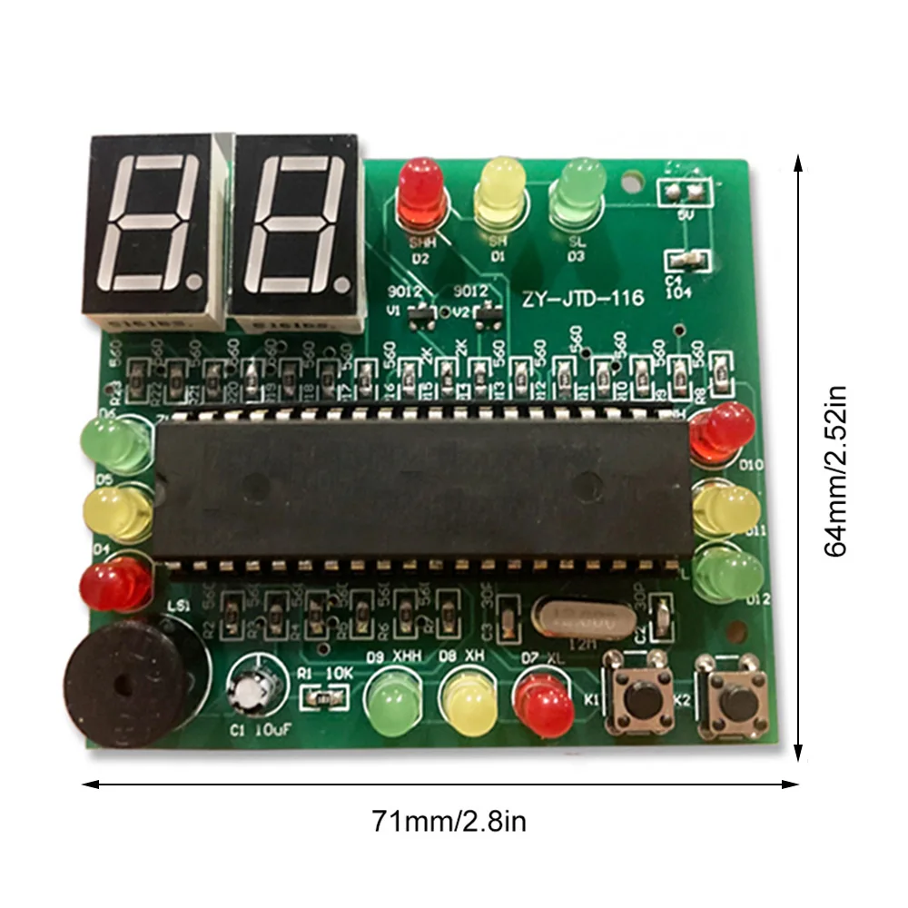
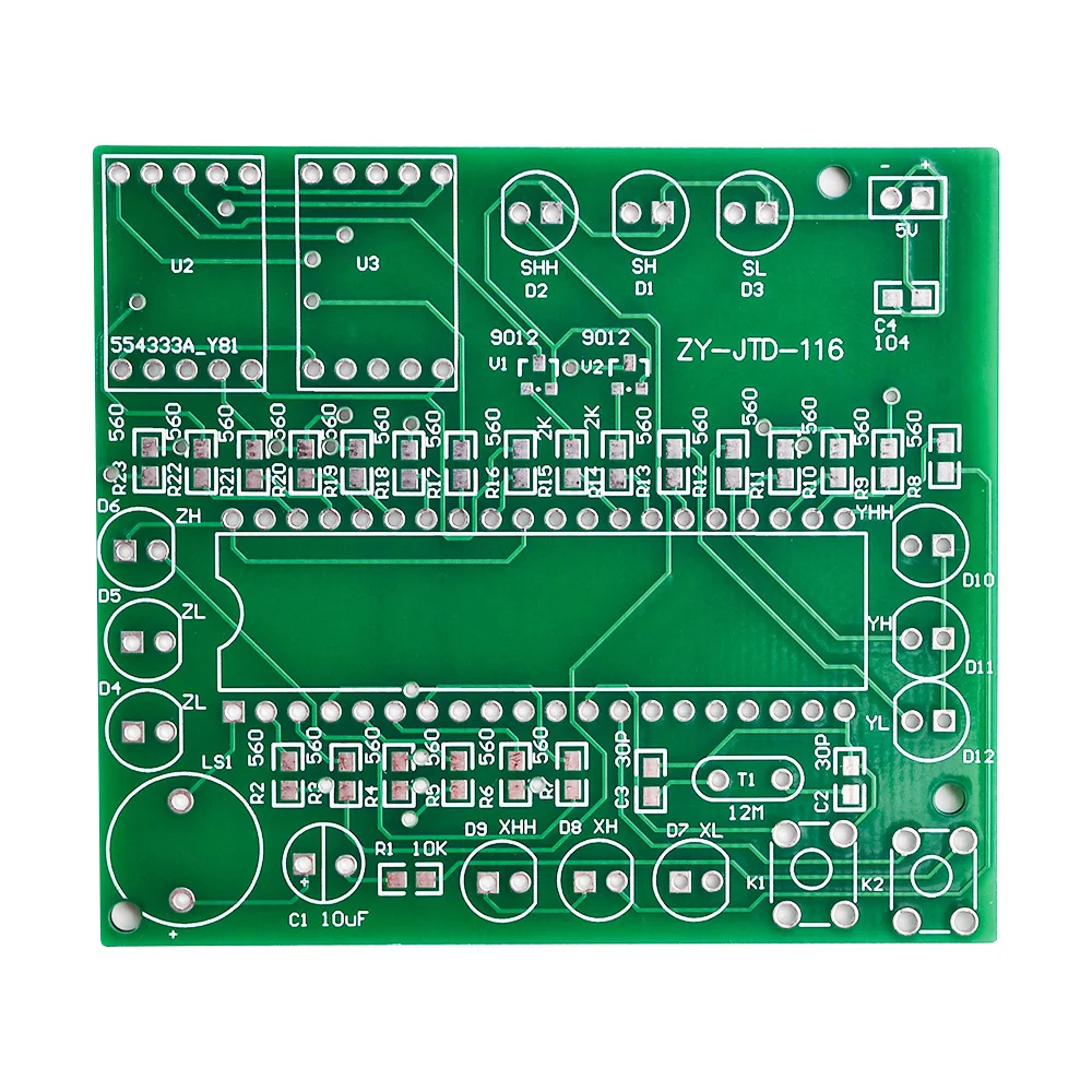
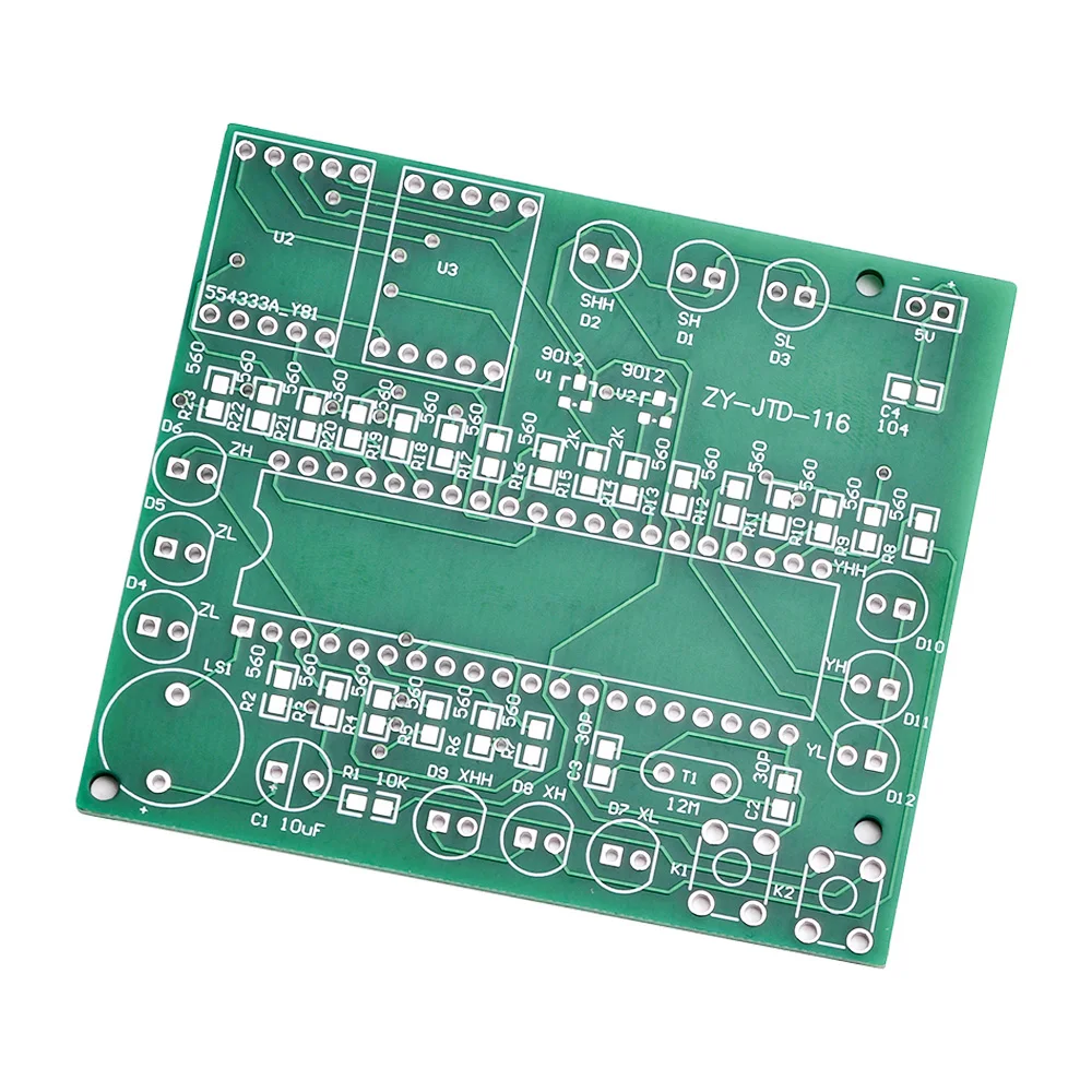
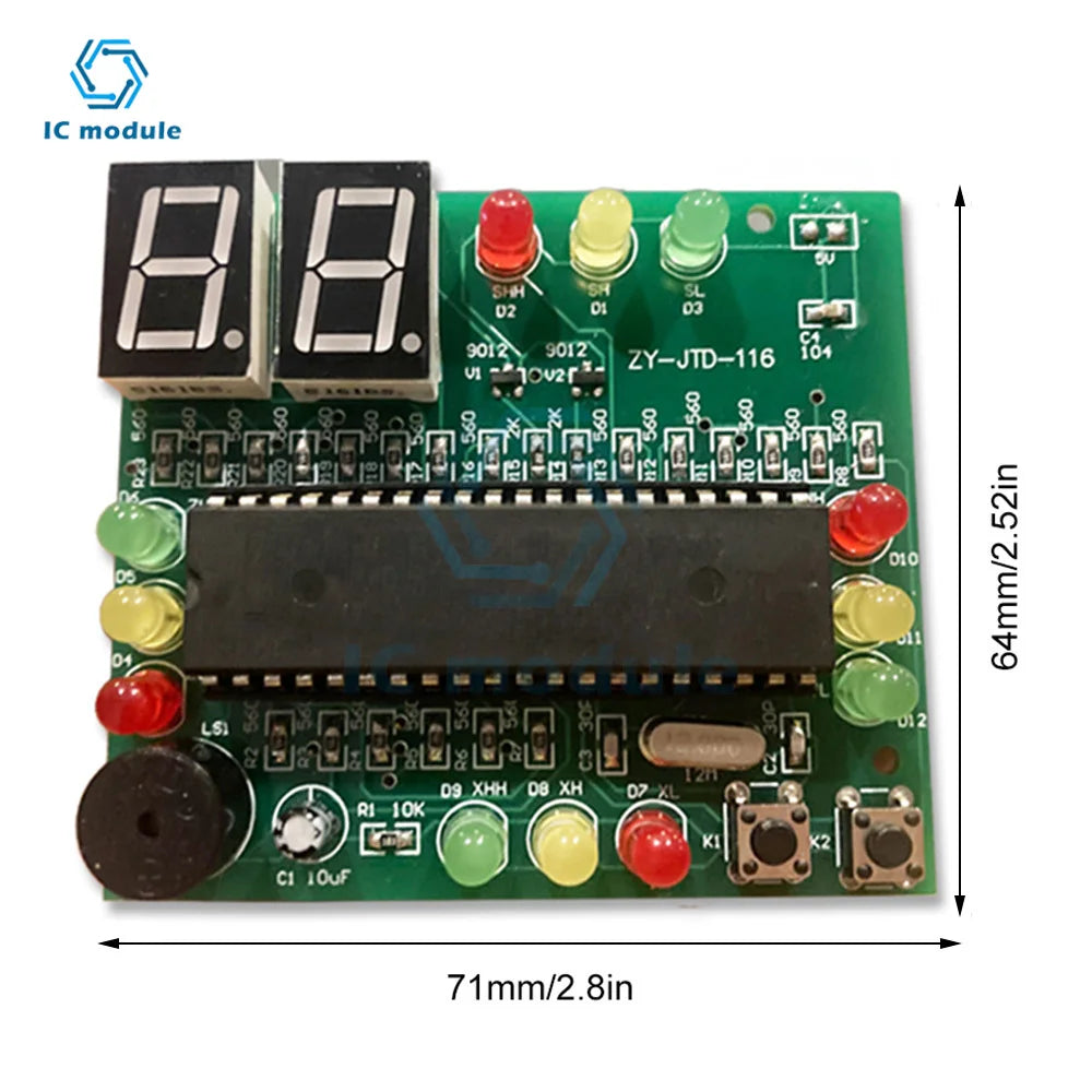
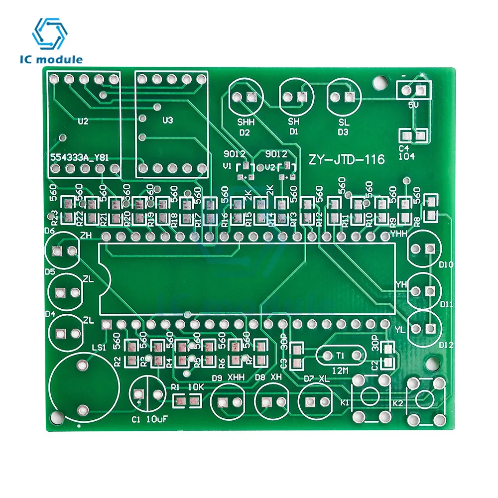
Dimensions : 71*64MM
Color : as picture shown

Features:
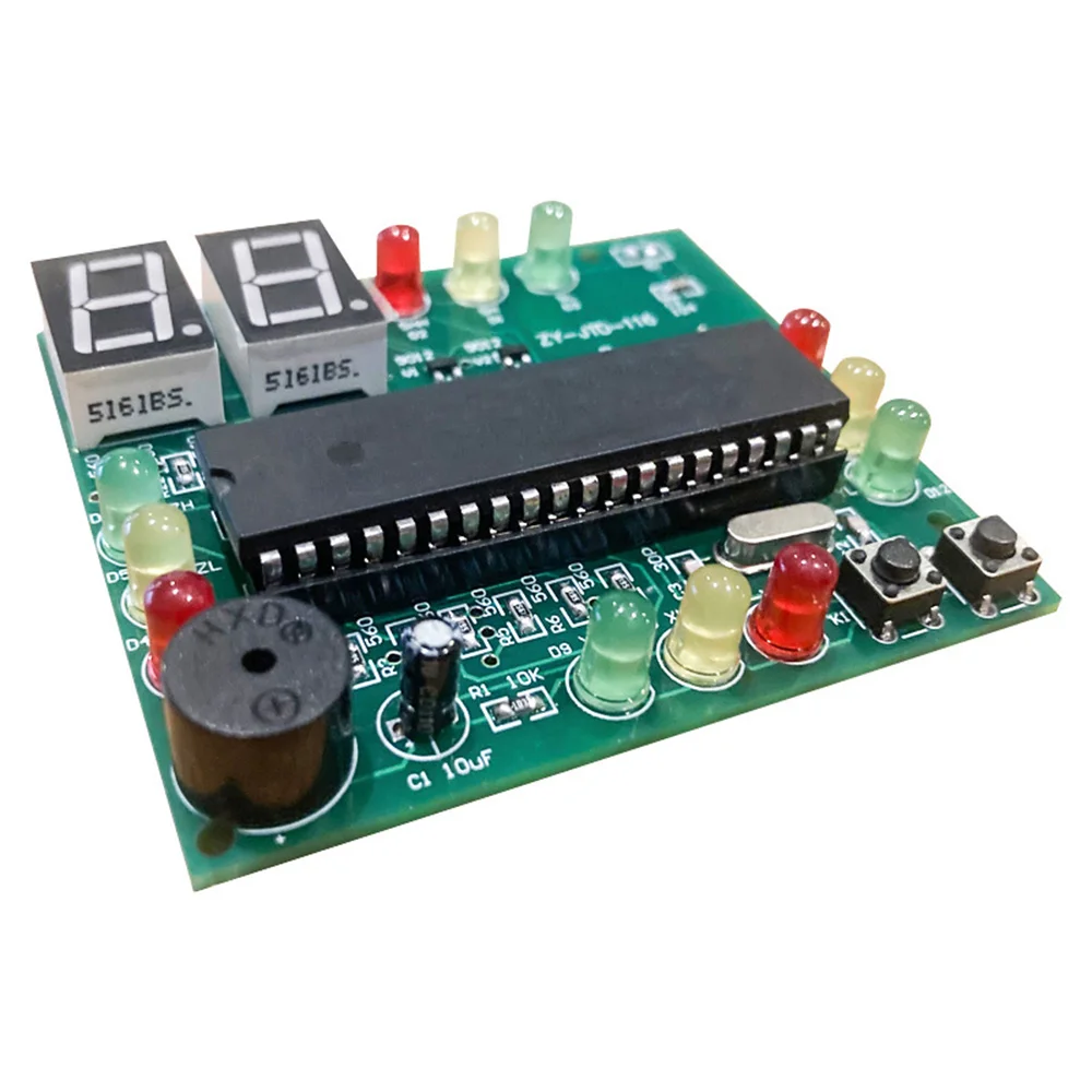
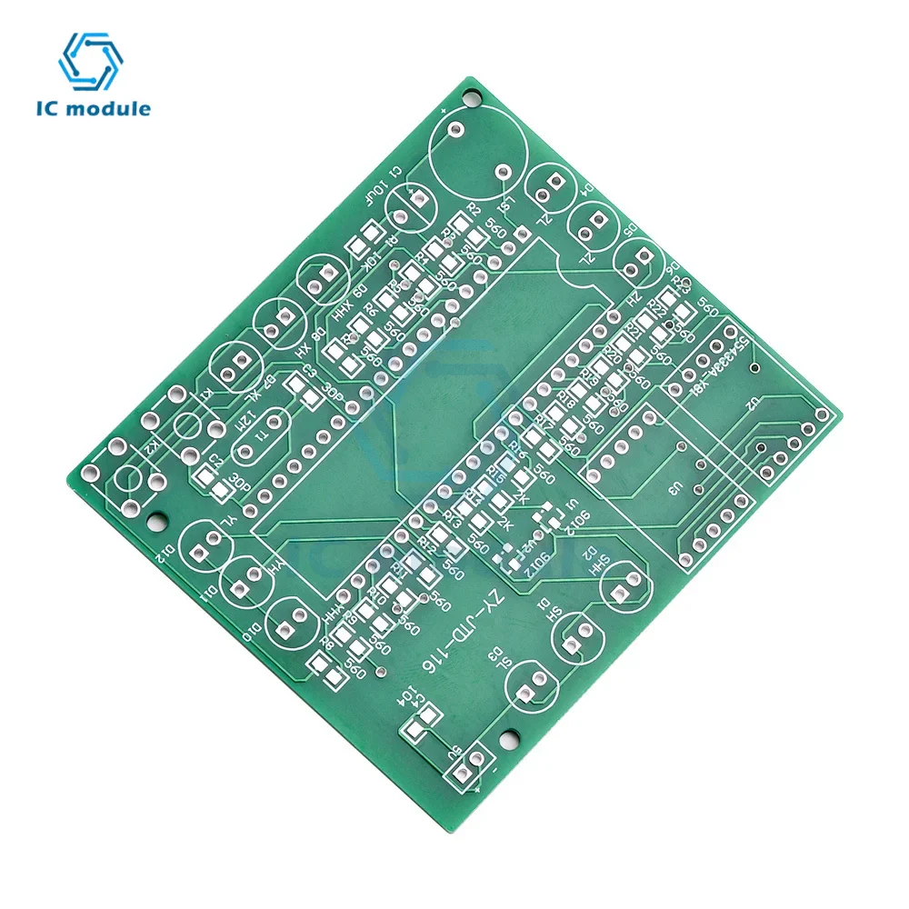
High quality fiberglass board
clear texture
Soldering is easier
Higher fault tolerance
Suitable for all kinds of DIY creations for hobbyists
Product parameters:
Color: as picture shown
Dimensions: 71*64MM
Power supply voltage: DC 5V
Product Description:
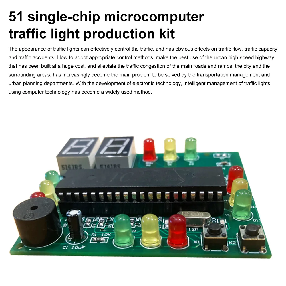
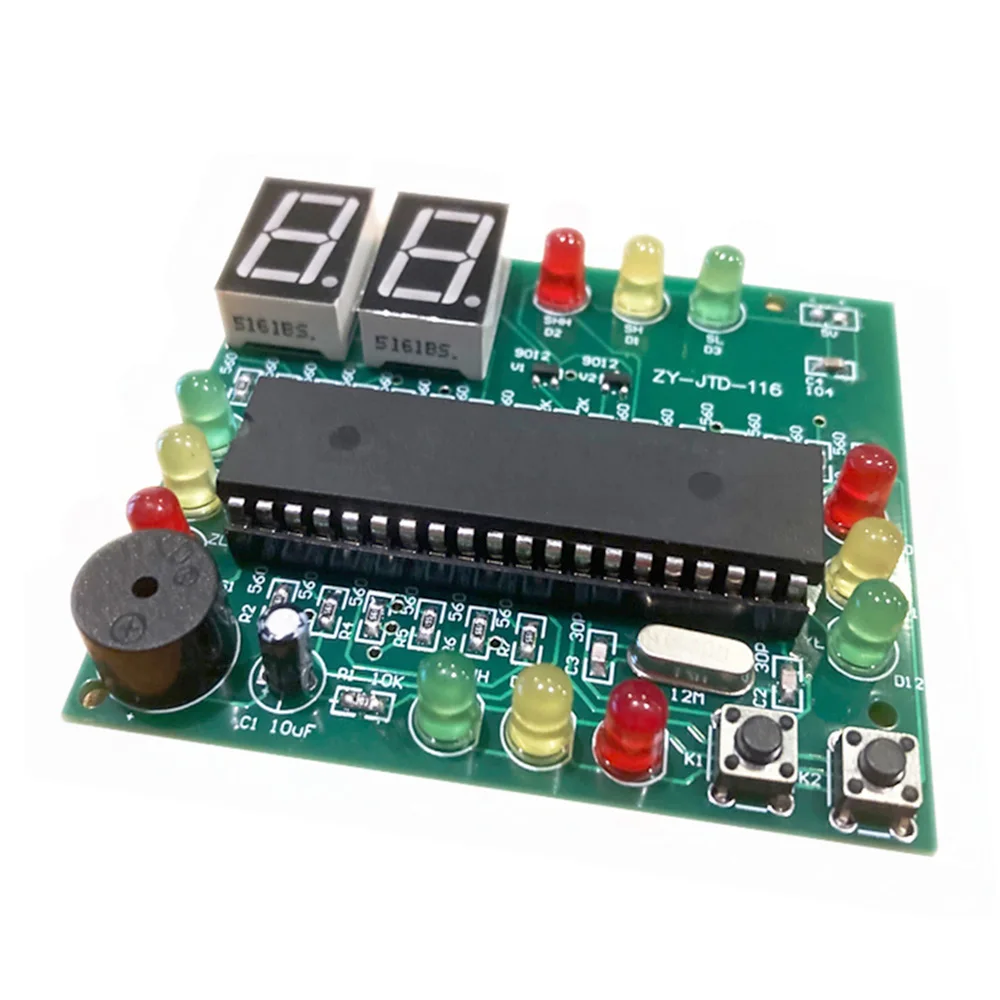
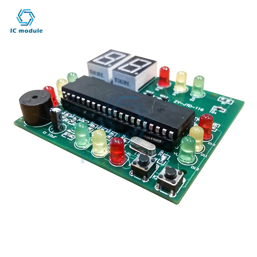
51 The traffic light simulation design of the single-chip microcomputer, through the programming of the single-chip microcomputer, control the change of the digital tube display and the LED on and off. There is a late-night mode, press the button to enter the late-night mode, the yellow lights in four directions flash to remind vehicles to pay attention to passing vehicles, and the time for the green light to pass can also be adjusted by pressing the button.
The appearance of traffic lights enables traffic to be effectively controlled, and has obvious effects on dredging traffic flow, improving traffic capacity, and reducing traffic accidents. How to adopt appropriate control methods to maximize the use of urban expressways that cost a lot of money to alleviate the traffic congestion of main roads and ramps, cities and surrounding areas has increasingly become the main problem that transportation management and urban planning departments need to solve urgently. question. With the development of electronic technology, using computer technology to intelligently manage traffic lights has become a widely used method.
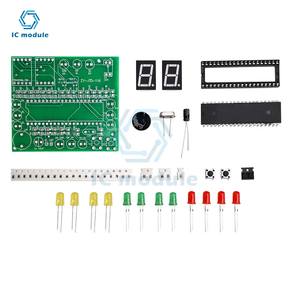
Kit description:
The appearance of traffic lights enables traffic to be effectively controlled, and has obvious effects on dredging traffic flow, improving traffic capacity, and reducing traffic accidents. How to adopt appropriate control methods to maximize the use of urban expressways that cost a lot of money to alleviate the traffic congestion of main roads and ramps, cities and surrounding areas has increasingly become the main problem that transportation management and urban planning departments need to solve urgently. question. With the development of electronic technology, the use of computer technology to intelligently manage traffic lights has become a widely used method.
Design a traffic light control circuit at the intersection of Shiyu, requiring the vehicles on the main lane and the arterial road to run alternately, and the time of each passage is set to 25S for the main road and 20S for the secondary road;
The yellow light is required to be on for 5 seconds before changing the running lane; 3. When the yellow light is on, it is required to flash once every second;
Countdown seconds display;
Sound prompt;
When there is a need to pass in special circumstances, the traffic lights can be considered to be controlled. The above are the control functions of the traffic lights at the current common intersections. In order to demonstrate the effect, three colors of light-emitting diodes are used here to simulate the traffic lights.
Soldering Tips:
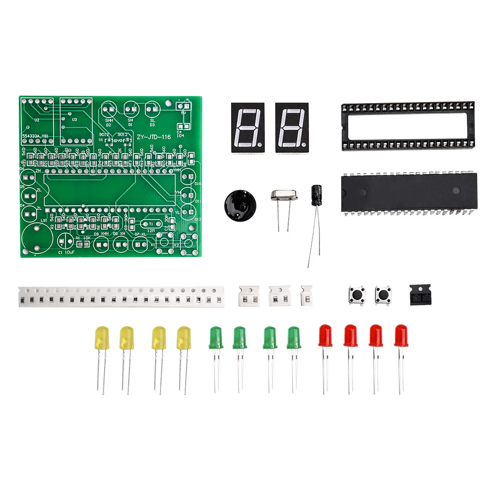
Solder the chip resistors and chip capacitors first. The chip components are small and easy to lose. Pay attention to disassembly and assembly.
The welding sequence of the components is to start welding from the small ones, and then to the tall ones. 3. For the soldering of SMD components, first put solder on one pad, then use tweezers to hold the component and align it with the position, put the component on while melting the solder, remove the tweezers and electric soldering iron after setting the position, and then solder the other with solder side pads.
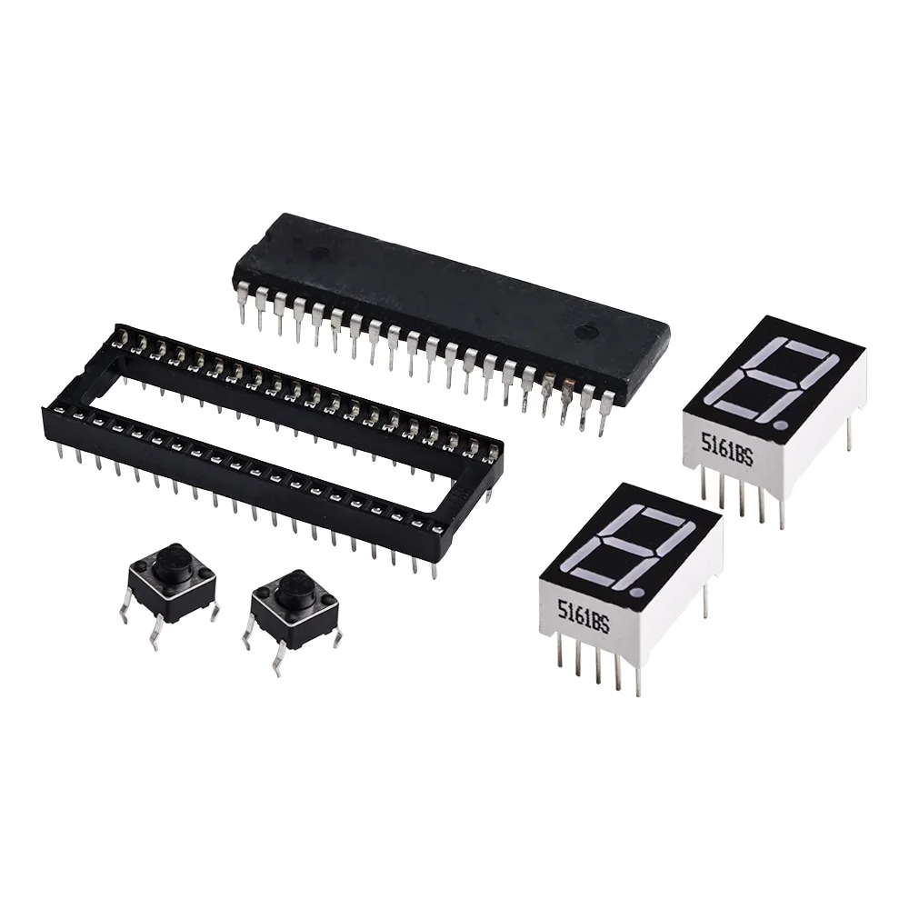
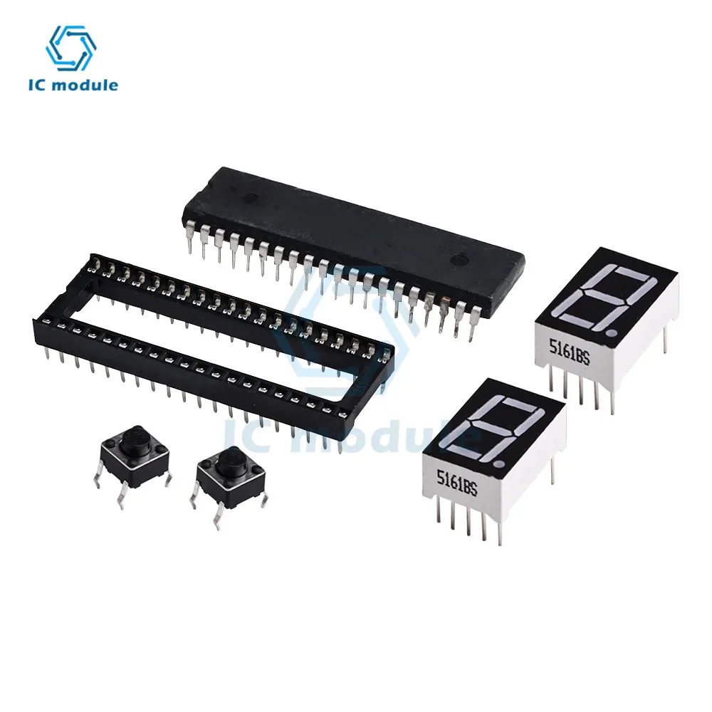
Then solder the integrated chip base, pay attention to the corresponding direction of the notch.
The short leg of the light-emitting diode is the negative pole, which corresponds to the solder hole on one side marked with a horizontal line on the board. Please refer to our physical map for the location of the red, yellow and green lights.
Both the electrolytic capacitor and the buzzer are positive with long legs, and the digital tube pays attention to the position of the decimal point.
Pay attention to check whether there is any problem such as tin-stained short circuit or insufficient tin soldering, and then supply 5V voltage, pay attention to the positive and negative poles.
Product List:
1X signal light kit
Note: The product should be assembled by DIY and not a finished product, so it needs to be welded by yourself!